For a larger view of images, right click on the image and select "Open in a new tab"
Link to: Catalog
Soft shift valves shift 3-5 times slower than standard valves to reduce shock in the hydraulic system and reduce the in-rush current. The shift times are still fast enough to barely effect the machine performance.
Commonly used in balers and compactors.
Compare to: Nachi SS-G01-__-FR-E115-E31
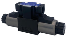
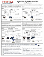
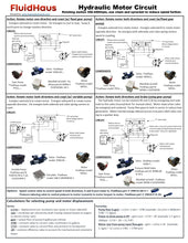
Hydraulic Directional Control Valves are used to control the hydraulic oil flow path to an actuator (cylinder or motor). The variety of spool options available allow for various movement types based on the application requirements of your cylinder or motor. Proven high quality robust valve design successfully designed into many high volume applications.
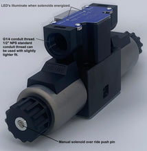
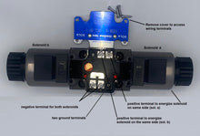
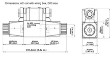
- Wiring terminal box with 1/2" (G1/2) conduit connection
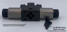
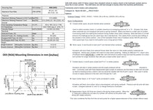
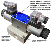
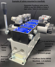
- D03 (NG6) Cetop mounting. Can be mounted to standard available subplates and bar manifolds.
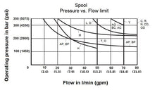
- Maximum flow of 21 gpm for DC power and 15.8 gpm for AC (reference Solenoid Power limit chart)
- Maximum working pressure = 4560psi (315 Bar)
- 3-position, 4-way, Spring centered, energize to shift
- Double solenoid operated
- Removable Coil
- Valve can be mounted in any direction
- LED illuminate’s when power is supplied to the connector/coil.
- NBR Buna Seals
- Four fastening screws included, M5x45mm long
- White label with no logo for OEM manufacturers.
- Weight = 4.3 lbs (1.95 kg)
- Solenoid Power: DC=30watts, AC=50VA holding and 220VA inrush
Options:
Solenoid Voltage: 12VDC, 24VDC, 110VAC (50 or 60 hz), 220VAC (50 or 60 hz)
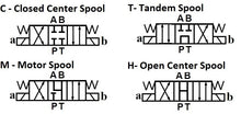
Spool Configurations:
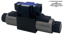
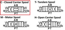
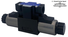
C: Closed center spool, all ports blocked when centered.
Useful to switch actuator directions and to fully stop cylinder or motor when centered. Make sure there is a relief valve to protect overrunning loads from spiking the pressure during sudden stops when centering. Note that there is some leakage of oil across the spool in the center position and slow drifting of the actuator could be possible.
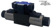
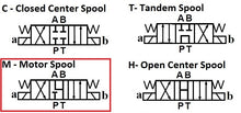
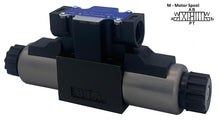
M: Motor spool, A and B ports to tank and P port blocked when centered.

Actuators will move freely from external forces when the valve is in the center position. Motors and cylinders will coast to a stop when centering. Adding an A&B port P.O. check valve under this valve will ensure a positive stop and hold the position of a motor and cylinder for longer durations than with just a closed center spool valve C.
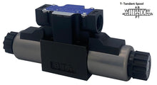
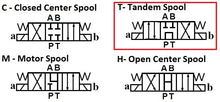
T: Tandem Spool, A and B ports closed and P to T in center position:

Actuators will stop in center position and the supply pressure will be directed to tank. Commonly used with fixed displacement gear pumps so pressure can flow direct to tank and not build up heat by blowing across a relieve valve as would be needed with the M and C spool.
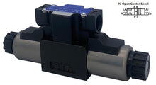
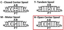
H: Open Center Spool, A, B P and T ports connected in center.
Actuators will freely move when valve is de-energized and spring centered. Pressure and all ports will drain to tank. Energize solenoid “a” and “b” to change direction of actuator.
R: Regeneration Spool: Closed ports in spring center position. When “b” side shifted the rod side of a cylinder will connect to the piston side combining the flows for a higher speed extension of the cylinder.

Actuator will stop in the center position. When “a” side is shifted, Pressure will go to the B port (typically rod side of cylinder) and the A port (typically piston side of cylinder) will go to tank for retracting the cylinder. When the “b” side is shifted the rod side and piston side are connected to pressure in regeneration, creating a higher extension flow. Note the extend for will be reduced by the area of the rod.
Solenoid Power Limit to shift valve based on spool type, flow, and pressure:

Mounting Pattern of mating surface (mm):

High volume OEM series production available per request.


