Stocked items ship the same to next business.

D03 (NG6): Hydraulic Manual Lever Control Valve: 21 GPM: 4560 psi Media 1 of 28
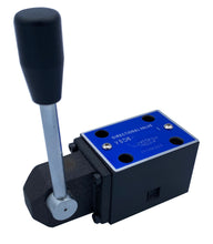
D03 (NG6): Manual Lever Hydraulic Control Valve:  21 GPM: 4560 psi
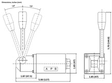
Dimensions D03 (NG6): Hydraulic Manual Lever Control Valve: 21 GPM: 4560 psi Media 1 of 28
D03 (NG6): Manual Lever Hydraulic Control Valve:  21 GPM: 4560 psi
  • Load image into Gallery viewer, D03 (NG6): Hydraulic Manual Lever Control Valve: 21 GPM: 4560 psi Media 1 of 28
  • Load image into Gallery viewer, D03 (NG6): Manual Lever Hydraulic Control Valve:  21 GPM: 4560 psi
  • Load image into Gallery viewer, D03 (NG6): Manual Lever Hydraulic Control Valve:  21 GPM: 4560 psi
  • Load image into Gallery viewer, Dimensions D03 (NG6): Hydraulic Manual Lever Control Valve: 21 GPM: 4560 psi Media 1 of 28
  • Load image into Gallery viewer, D03 (NG6): Manual Lever Hydraulic Control Valve:  21 GPM: 4560 psi
  • Load image into Gallery viewer, D03 (NG6): Manual Lever Hydraulic Control Valve:  21 GPM: 4560 psi
  • Load image into Gallery viewer, D03 (NG6): Manual Lever Hydraulic Control Valve:  21 GPM: 4560 psi
  • Load image into Gallery viewer, D03 (NG6): Manual Lever Hydraulic Control Valve:  21 GPM: 4560 psi
  • Load image into Gallery viewer, D03 (NG6): Manual Lever Hydraulic Control Valve:  21 GPM: 4560 psi
  • Load image into Gallery viewer, D03 (NG6): Manual Lever Hydraulic Control Valve:  21 GPM: 4560 psi
  • Load image into Gallery viewer, D03 (NG6): Manual Lever Hydraulic Control Valve:  21 GPM: 4560 psi
  • Load image into Gallery viewer, D03 (NG6): Manual Lever Hydraulic Control Valve:  21 GPM: 4560 psi
  • Load image into Gallery viewer, D03 (NG6): Manual Lever Hydraulic Control Valve:  21 GPM: 4560 psi
  • Load image into Gallery viewer, D03 (NG6): Manual Lever Hydraulic Control Valve:  21 GPM: 4560 psi
  • Load image into Gallery viewer, D03 (NG6): Manual Lever Hydraulic Control Valve:  21 GPM: 4560 psi
  • Load image into Gallery viewer, D03 (NG6): Manual Lever Hydraulic Control Valve:  21 GPM: 4560 psi
  • Load image into Gallery viewer, D03 (NG6): Manual Lever Hydraulic Control Valve:  21 GPM: 4560 psi

D03 (NG6): Manual Lever Hydraulic Control Valve: 21 GPM: 4560 psi

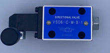
VSD6-C-M-S-I
Regular price
$114.00
Sale price
$114.00
Regular price
Sold out
Unit price
per 
Tax included. Shipping calculated at checkout.

link to: Catalog

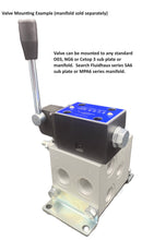
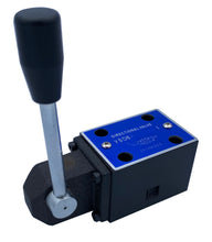
Hydraulic Directional Control Valve – Manual Operated.  Proven high quality robust valve design successfully designed into many high volume applications.

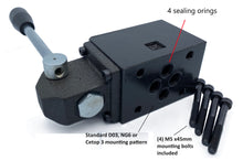
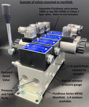
  • D03 (NG6) Cetop mounting.  Can be mounted to standard available subplates and bar manifolds.
  • Maximum flow of 15.8 gpm
  • Maximum working pressure = 4560psi (315 Bar)
  • Manual Lever operated
  • 3-position and 2-Position
  • With automatic spring return of spool or detent to hold position until force is applied to the lever
  • Valve can be mounted in any direction
  • NBR Buna Seals
  • Use with mineral based hydraulic fluid.
  • Four fastening screws included, M5x45mm long
  • White label with no logo for OEM manufacturers.
  • Weight = 3.6 lbs (1.62 kg)

Options:

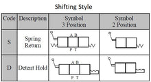
Shifting type: automatic spring return or detent to hold until force applied to lever

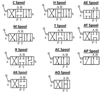
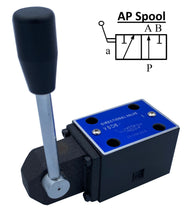
Spool Configurations:

Spool Configurations:

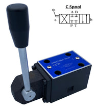
C:  Closed center spool: all ports blocked when centered. 3-Position:


     Useful to switch actuator directions and to fully stop cylinder or motor when centered.  Make sure there is a relief valve to protect overrunning loads from spiking the pressure during sudden stops when centering.  Note that there is a small amount of oil leakage across any spool type valve manufacturer for smooth shifting. This means there could be slow drifting of the actuator in the center position.  Use a Pilot Operated Check Valve series VMCP6 with the M Valve spool type if you need to hold position over a long period of time.

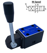
M:  Motor spool: A and B ports to tank and P port blocked when centered.  3-Position:

Motors and cylinders will coast to a stop when centering.  Actuators will move freely from external forces when the valve is in the center position.  Adding an A&B port P.O. check valve under this valve will ensure a positive stop and hold the position of a motor and cylinder for longer durations than with just a closed center spool valve C.

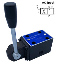
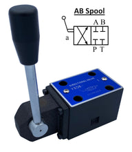
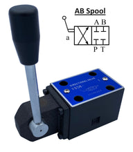
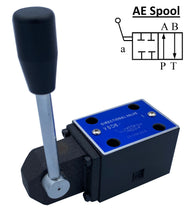
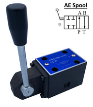
AC:  Pressure to A port and B port to tank in neutral position.  2-Position:

In the normal position pressure goes to the A port and the B port goes to tank.  When lever shifted, Pressure directs to B port and A port to tank.  During transition between spool positions all ports are blocked.  Can be used when an actuator needs to be only extended or returned or when a motor will only rotate clockwise or counterclockwise.

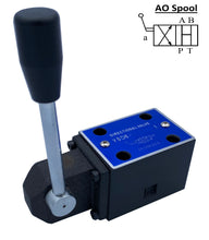
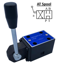
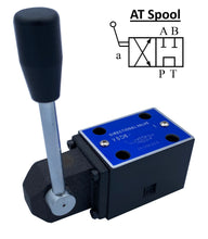
AO: All Ports Open to Tank in Normal Position. 2-Position:

In the normal position all ports are open to tank.  Shifting the lever sends pressure to the B port and A port to tank.  Can be used to extend cylinders that are gravity, spring or external force returned.

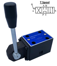
T:  Tandem Spool: A and B ports closed and P to T in center position. 3-Position:


Actuators will stop in center position and the supply pressure will be directed to tank.  Commonly used with fixed displacement gear pumps so pressure can flow direct to tank and not build up heat by blowing across a relieve valve as would be needed with the M and C spool.

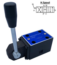
H: Open Center Spool: A, B, P and T ports connected in center. 3-Position:

Actuators will freely move when valve is de-energized, and spring centered.  Pressure and all ports will drain to tank.  Energize solenoid “a” and “b” to change direction of actuator.


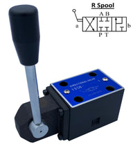
R: Regeneration Spool: Closed ports in spring center position.  When “b” side shifted the rod side of a cylinder will connect to the piston side combining the flows for a higher speed extension of the cylinder.


Mounting Pattern of mating surface (mm):


High volume OEM series production available per request.
Thousands in use in various applications.